 in Russian
in Russian
The hydrodynamics of a ship in a storm is not limited to the hull below the calm-water waterline. In a storm, the operating waterline varies between the bilge and the deck, causing unpredictable waves forces on the hull as well as the possibility of slamming on flat surfaces and the flared side of the vessel.
The present work reveals the early stage of a design process for a hull form taking into account the range of changing of waterline, that insures stability under severe heave. With this approach it is possible to reduce the metacentric height, which minimizes roll resonance. The concept is a consistent ship design; conventional naval architectural approaches will still be needed for successful solutions for reducing the pitching and yawing of the vessel, and also as a necessary condition for using active side stabilizers and other seaworthiness improvements.
From a design standpoint there is a contradiction in dynamical properties of a ship; improving one leads to the deterioration of another.
So, an attempt to increase the initial static stability results in increased rolling of the ship in severe seas leading to, potentially catastrophic problems with the strength of the hull structure. It is a paradox — attempting to improve static stability may lead to an increased likelihood of capsizing as a result of strong resonant rolling or broaching.
Significant difficulties in the operation of a vessel may occur when the freeboard and reserve buoyancy are too large for the vessel, particularly with the implementation of other requirements without consideration of green water on deck, or by installation of unwieldy life-saving equipment, that can pose a danger for mariners.
Let us consider some elements of hull shape optimization and general ship geometry from the standpoint of achieving the best seaworthiness of the vessel.
A ship design for seaworthiness, considers a hull form with a sharp cruiser stern and no increased freeboard in the bow section. Such a vessel has no flare and no bulbous bow, as too much volume forward makes a ship pitch. Such hull form is capable of maintaining operability in all-weather conditions.
Such a design has almost constant waterplane area as a function of draft and low damping in heave. As a result this vessel’s stability in waves is essentially constant; thus the minimum stability occurs at the design condition. To remedy this situation the static stability with varying draft must be changed.
Modern vessels with a wide transom stern and with flare and increased freeboard at the bow, experiencing intensive pitching in longitudinal waves. In this mode of sailing, the hydrodynamic effect of excessive volumes in the extremities is essential when the hull of a vessel moving thru the wave crest and over the wave through. However, the hydrostatic approach to this problem is not contrary to the implementation of the proposed scheme of the hull design. The objective of this work is finding a compromise between the proposed design scheme and modern hull forms.
2.1. Hydrostatic peculiarities of a highly seaworthy vessel |
The hydromechanics of a ship in extreme seas includes some design paradoxes, which significantly affect the seaworthiness of non-optimized vessels, and, in fact, determines the possibility of the all-weather or the special modes of vessel operation in accordance with the vessel’s design purpose.
Some elements in the hull forms design are well established in the maritime history, and now their use is somewhat weakened in favor of efficiency of cargo handling, increased volumetric capacity, or sometimes just for aesthetic reasons.
Identification of and optimal resolution of the hydrometrical paradoxes is defined by accounting for the adverse effects of weather through specifically designed lines. Let us consider some specific elements of the hull form:
The metacentric radius r (KM) has cubic dependence on the breadth B.
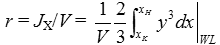 |
(1) |
In a storm conditions external forces and moments are created by the curved sea surface and this affects the stability of a ship:
 |
(2) |
Note that this moment is not balanced by the weight of the vessel; this moment reaches its maximum value for vessels with a wide transom sterns. This moment may be dangerous for multihull vessels, because it is directly dependent on the area of waterplane, since the metacentric radius (KM) changes as the cube of the offsets.
The formula for the metacentric radius is consistent with the subsequent results of hydrostatic calculations at large roll angles. To be able to assess the stability of the vessel as a rigid body in a storm, fix the center of gravity at the z-coordinate of the metacenter at a given draft.
To achieve smoothness of roll in a storm, an captain always tries to reduce the metacentric height by raising the KG of the vessel towards the KM-value (fig. 1). This decreases roll motions because of the suppression of external forces by the inertia of the ship. This process is described by the “captain’s” formula for initial stability:
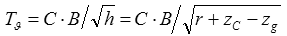 |
(3) |
If the center of gravity is significantly above the waterline, the ship becomes vulnerable to impact by a single wave from the side.
The contours of the stations in the midship section of the optimized vessel (fig. 2) are close to a circle, and it has a beam-to-draft ratio (B/T) of about two. Accordingly, the z-coordinate of the metacenter will be at about the level of the current waterline. Then, the effect of a single wave relative to the center of gravity that is located near the metacenter. Such an effect produces a relatively small moment and does not lead to significant roll motions.
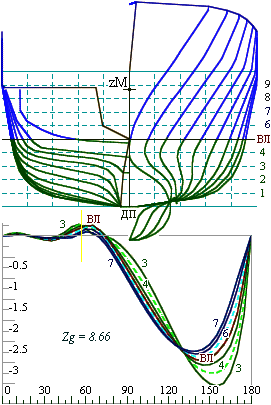 Figure 1. Top: Body plan for conventional hull form; Bottom: the static stability diagrams of the ship for five waterlines, the z-coordinate of the center of gravity is fixed at the position of the metacenter at the design draft. The natural stable position of the ship hull is “keel up” |
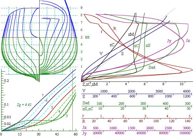
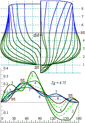 Figure 2. Top: Body plan for optimized hull form; Bottom: the static stability diagrams of the ship for five waterlines, the z-coordinate of the center of gravity is fixed at the position of the metacenter at the design draft. The metacentric height of the optimized ship can be safely brought to zero at the design draft. GM will be positive for any other draft and there is a large reserve of stability. |
The hydrostatic and Froude-Krylov moment in pitch of a long vessel cannot be reduced by increasing the KG, because the longitudinal metacenter is too high. Thus the lines can only be optimized to decrease of external forcing, so the ship will simply contour the waves.
Once the hydrostatic and Froude-Krylov forces are minimized, then a further decrease of pitch and roll motions can be achieved by considering the hydrodynamics of the hull in trochoidal waves. This is a separate problem considered in (Khramushin, 2009)
Here we focus on a simple optimization of lines by consideration of Froude-Krylov and hydrostatic forces. The main approach is the method so-called non-contradictory design.
The expected technical result is a displacement ship with a relatively deep draft and pointed extremities (cruise stern and “reclined stem” [stem inclined back]). The reserve buoyancy is concentrated in the in the midship section. The GM is minimal at the design draft. Thus, the GM increases with any variation of the draft. This is achieved by special design of the lines (Khramushin, 2011). The next subsection is focused on analysis of the hydrostatics of the midship section only.
3.1. Analysis of Metacentric Height at Design Draft |
The stability of a wall sided ship is characterized by the value of metacentric height h (GM). The variation of GM during heave motions is caused by changes of the vertical position of the center of buoyancy zC (KB) and volumetric displacement. The GM increases with an increase of KB and decreases with an increase of the displaced volume. We also fix the center of gravity. The transverse moment of inertia of the waterplane Jx is constant since wall-sidedness is assumed,
| (4) |
In the case of a wall-sided midship section, the minimum of the vertical position of the metacenter zM (KM) occurs for B/T=3.
Accordingly, for a ship with B/T > 3 , the minimum zM (KM) is achieved for a flared configuration due to the rapid increase in JX (z) on the hydrostatic curves (right-hand side of figs. 3 & 4). The behavior of such ship in a storm includes significant pitch and roll, however, she is capable of contouring waves.
A vessel with good seaworthiness should have B/T £ 2. Thus a minimum KM can be achieved at the design draft. Such a ship must have a tumblehome shape at the waterline.
Ship lines with a round midship section does not have a clear minimum of KM (zM in fig. 3). Therefore it becomes important to maintain positive metacentric height, because the reserve stability is small and roll motions may reach large amplitudes. An increase in stability leads to an increase of motions.
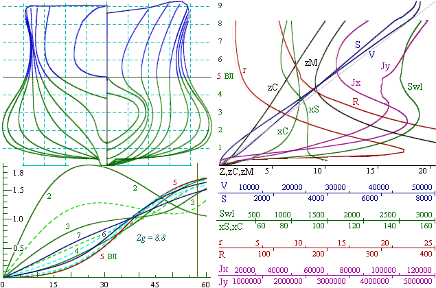
The minimum of the KM is shown most clearly for the configuration in fig. 4. The stations have concave shape at the design waterline — the KM as a function of draft has a minimum around the DWL.
Stability in storm conditions should be provided by shape of the hull as the draft varies. This effect can be easily achieved for a ship design with concave stations at the waterline (fig. 4) and — with the most difficulty for a ship with round stations (fig. 3).
Hydrostatic curves provide a quantitative description of the forms (right-hand side of figs. 3 & 4). The stability is associated with the condition of mutual compensation of the changes of moment zC·V relative to base plane, through the moment of inertia of the waterplane JX. Geometrically, it is the choice between wall-sided, flared or tumblehome configuration of the midship section at the waterline. In fact, this is the optimization of the angle of side slope at the design draft. The algorithm was implemented in a computer program – “Hull” with Russia state registration number 2010615849.
The GZ curve (figs. 3 & 4, bottom left) is computed for a variety of drafts at a fixed value of KG, the curve with zero metacentric height (labeled “5”) corresponds to the design draft, and other curves (3, 4, 6 & 7) — show positive initial stability as the draft variaties.
All calculations were performed for a fixed position of the center of gravity zg (KG), placed exactly that the metacenter at the design draft, where the initial stability is equal to zero (hWL = 0).
The graphs on the right show the hydrostatic curves computed for the vessel depicted on the left.
The paper presents the ways to optimize the initial elements of a ship’s lines based on hydrostatic calculations. This provides a reliable quantitative estimate of the performance of the vessel in a storm. This hydrostatic assessment of seaworthiness is applicable to all classes of ships and vessels.
All these design solutions and seaworthiness estimations must be explained by operational guidance onboard of ship’s bridge and on shore services. This knowledge can enhance operability of the ship in complex storm and ice conditions. These hydrostatic assessments make-up the foundation for further deeper design optimization based on the fluid mechanics interaction between the hydro- and aero-mechanics of the ship in storm sea and hurricane winds.
The author is grateful to Dr. Art Reed for his detailed editing that has greatly improved clarity and readability of the text.
Khramushin V., (2009) “Key Design Solutions and Specifics of Operation in Heavy Weather (Fluid Mechanics Approach to Stabilization of Ship in Heavy Seas)” Proceedings. 10th International Conference on Stability of Ships and Ocean Vehicles. STAB-2009, S-Petersburg, Russia. pp. 473–482. ( http://shipdesign.ru/Khram/Art/STAB2009-eng.html )
Khramushin V. The ship, the stability in a stormy operation. Patent application (19) RU (11) 2011129192 from 12.07.2011. Sаkhalin State University. ( http://shipdesign.ru/Invent/06.html , in russian).